
Hideaway Strobe Light Installation Questions for Upfitters
By UNIT SIGNAL ·
Before ordering hideaway strobes, decide whether the location is inside a headlamp or tail lamp assembly, or on an external mounting surface. Have the upfitter review available space, the effect on normal lamp functions, the installation drawing and service access. An internal-mount option describes what the strobe can accommodate. It does not establish that a specific lamp housing can be modified for that use.
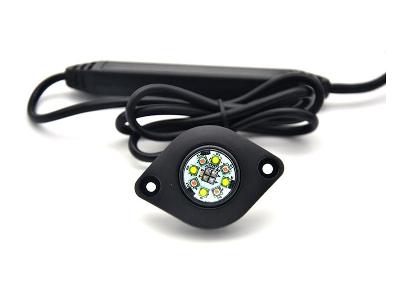
Decide whether internal mounting is justified
Internal mounting may be considered when the fleet wants a low-profile installation and there is a suitable host assembly. Identify the lamp part number, vehicle version and the side of the vehicle. Two versions of a visually similar lamp can have different reflectors, rear covers, mounting points or internal wiring. If the fleet has several lamp versions, ask the upfitter to determine which can use the same design before ordering a single kit across all vehicles.
External mounting can be a better evaluation path when the host lamp should remain untouched. Look for a location that gives the intended view, offers suitable support for the approved mounting hardware and allows technicians to reach the connector. The external location still requires a wiring and sealing plan. Compare it with an internal installation on the same criteria instead of equating the two solely by housing size.
| Location | Leading acceptance concern |
|---|---|
| Inside a headlamp assembly | Clearance, effect on original optics and heat around the intended location. |
| Inside a tail lamp assembly | Original functions, internal space, cable exit and access during service. |
| External surface | Mounting face, gasket contact, warning view and protected harness. |
Measure the housing where the module will actually sit
Photograph the front and rear of the assembly and take measurements at the potential mounting points. Record the available depth with nearby covers, trim and equipment installed. Mark the orientation and the cable bend needed behind the flange. A reflector can create a narrow clearance where a product picture suggests plenty of room. It can also screen part of the strobe when viewed from a relevant angle.
Agree who will check whether the host lamp can be modified without compromising its function, sealing or approval for the destination. The installer should identify the approved location and method for any proposed opening before altering a lamp. Where the lamp manufacturer or vehicle documentation limits modification, choose a different location or obtain the necessary review. Treat these decisions as part of the installation, not as specifications the strobe supplier can infer from a vehicle photo alone.
Separate product dimensions from cutout and flange dimensions
The U800 hideaway strobe light lists a body diameter of about 38.5 mm and a height of 18.8 mm. The listing describes a mounting flange and gasket. A body diameter, flange outside diameter and hole size serve different purposes. Use the latest instructions and template for the exact version to check the intended opening, how the flange sits and what clearance to leave for the lead.
Also check how the housing will be held after it is assembled. Ask which hardware is supplied and what the installer must provide. An installer may be able to mount the module but lose access to the screws once the lamp is in the vehicle. Ask the workshop to show how the unit would be removed on a finished vehicle. Where a flush appearance is important, include the installed face position in the approved drawing.
Review sealing, heat and wiring as separate issues
Identify the base or gasket surface, the wire exit, how the harness approaches the module and any new path for water or contaminants. An ingress rating for the hideaway describes the product under specified conditions. It does not establish the integrity of a modified headlamp, tail lamp or electrical joint. Have the upfitter define how the finished assembly will be inspected and how the original lamp will be checked again after the work.
The U800 is specified for 12–24 V and has separate connections for pattern selection, synchronization and alternation. The U1200 hideaway strobe light lists a 10–30 V input. Use the manual for the exact variant to establish connection points, triggers and allowed pairing. A wider operating voltage range does not establish matching wire functions or control compatibility. Use the U800 wiring diagram to identify the functions you need to check. Before connecting the module, verify the wire assignments against the instructions supplied with the unit.
Decide which vehicle variations need separate evaluation
For a vehicle with several light assembly versions, collect a sample or drawings for each version the fleet intends to fit. Look for differences in the rear covers, socket location, reflector depth and access once the lamp is back on the vehicle. Check the left and right assemblies separately when their internal space, wire routes or orientation differ. Even a small difference can change where the light can sit or how it can be serviced.
For an external installation, record the face angle and surrounding hardware for each proposed location. A low position behind a bumper edge may disappear from view at some approaches. Moving it to improve the viewing angle might change the clearance behind the mounting point. Check both the intended view and the actual installation space before deciding whether a common bracket or housing makes sense across the fleet.
Build an installation information pack before ordering
Ask for an assembly drawing that names the module, mounting components and harness version in the offer. The drawing or instructions should identify the applicable installation geometry and orientation. Request a separate wiring diagram with the intended input and trigger functions. Ask the upfitter to mark which parts of the design have been checked on the actual vehicle and which should be evaluated on a first installation.
Write the service plan on the same page. A failed module may need a new gasket, flange or connector when it is replaced. Record whether the original lamp must be removed, whether the installer can disconnect the strobe independently and which mounting components should be ordered as spares. If the vehicle already uses another hideaway module, include its drawing and the existing cutout so a proposed retrofit can be compared without guessing.
A clear scope also avoids pricing different assemblies as if they were the same. One quote may include a module and flange but leave the vehicle harness and finishing work to the upfitter. Another may quote a sample in a defined mounting configuration. Ask what is included and list the installer’s responsibilities for each, including work on the vehicle or host lamp. Begin with a sample when the job still depends on checking a new location or assembly.
Set a first-vehicle acceptance check
- Before fitting: compare the received module, gasket, flange and lead with the drawing and approved parts list.
- After assembly: inspect the mounting face and access, test normal vehicle lamp functions, and check the warning light modes that will be used.
- From the required approaches: observe the signal in a controlled area with trim and other equipment fitted.
- For fleet service: document the wiring revision, the location of joints and how the module and host lamp can be removed.
Evaluate the same points again if the fleet changes lamp assembly supplier, housing revision or the strobe variant. Store the final photos with the drawings so the next installer can see where the exact mount and cable were placed. Order spares by the accepted part numbers and include the applicable gasket or flange when it is needed for service.
Questions to resolve before committing to the installation
Can an existing opening be reused?
Measure it and compare the shape, thickness and surrounding surface with the instructions for the replacement. Check that the flange and gasket seat correctly and that the outlet and wiring clear the installed assembly. A quoted replacement diameter is not a substitute for evaluating the full opening and mounting face.
Can front and rear modules share a control setting?
Check the exact variants and diagrams for both units. Where a combined or alternating pattern is required, request the supported arrangement and verify it on the first vehicle. Save the settings with the harness record for maintenance and future replacement.
Is an external mount suitable if the original housing cannot be changed?
It may be, if the proposed position satisfies the viewing and mounting requirements. Identify the surface, bracket and cable protection, and check the installation from the required approaches. Keep the internal and external options separate in the quotation so the hardware for each is clear.
Send the actual lamp and installer details
Use the hideaway strobe range to shortlist models. Send UNIT SIGNAL photos of the lamp assembly or proposed surface with the vehicle and lamp part number, available dimensions, supply voltage, control requirements, quantity and destination. Include the mounting position and whether the installer has approval to modify the host lamp.