
Traffic Advisor Flash Patterns and Controller Selection
By UNIT SIGNAL ·
Specify a traffic advisor by what an approaching driver should see and what the vehicle operator needs to control. List the directional sequences, any separate warning flash and the required behavior when modes are selected together or power is interrupted. Then choose a bar, controller and harness as a documented combination. A product description that says “multiple patterns” is too broad to sign off an installation.
Identify the signal before choosing a controller
| Mode | Display to verify |
|---|---|
| Left | The sequence moves toward the approaching driver’s left. |
| Right | The sequence moves toward the approaching driver’s right. |
| Center-out | The sequence begins near the middle and proceeds outward on both sides. |
| General warning | A flashing display distinct from a directional instruction. |
The words left and right should refer to a stated viewpoint. Label it in the drawing and at the controller sign-off. A test observed from the front, or a video that has been mirrored, is easy to misread. For a rear-facing installation, photograph the complete display from behind and verify it with a second person who can see what appears when the operator presses each switch.
Some directional modules show a moving sequence; some installations use separate arrow elements. Confirm what the particular bar shows, including the first segment and the order of the movement. Treat general warning as a separate requirement. Do not infer that every bar can run warning and direction modes at the same time. The applicable road-work procedures and authorization for particular modes should be identified by the fleet before the controls are configured.
Ask what happens when two commands compete
Write down which mode should take priority if two inputs are active. For example, the fleet may specify what happens when the operator enables a separate general-warning switch while a direction mode is selected. Depending on the controller design, a warning input can override another mode or require the user to select one mode first. Verify the actual behavior, because having both options on the spec sheet does not tell you how they interact.
The driver also needs clear feedback during operation. If the controller uses indicator lights, determine whether they show the selected command or confirm the display’s output. In a vehicle where the bar cannot be seen from the cab, this distinction matters when diagnosing a connection fault. Include switch labels, feedback and the expected behavior if communication or power is interrupted in the procurement brief.
Read the bar and controller listings together
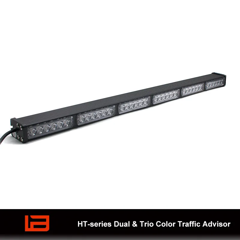
The HT-series traffic advisor lists three directional flash patterns as well as warning patterns, 12 V or 24 V supply options and several connection arrangements. It lists an optional four-switch controller. Specify which input voltage, bar and control configuration are being quoted before treating those listed options as part of a delivered kit.
Compare the HT-series with the DT-series traffic advisor if the fleet needs a different physical or control arrangement. Use the product pages to shortlist equipment, then request the configuration-level chart of supported modes and mounting dimensions. A family’s headline pattern count is less useful for buying than a simple row-by-row list of required functions the selected hardware can demonstrate.
Make the rear installation part of the comparison
Provide a rear photograph and a side drawing showing the proposed height and the area where the cable can enter the body. Include tailgates, lift platforms, ladders, racks or tailboards that may affect the view. Check it in the position used during the work. A display visible on a parked vehicle with all equipment stowed may be partly covered when the vehicle actually needs to give a warning.
Record the bracket type, panel and access for the fasteners and cable. Ask the installer to confirm the allowable mounting orientation for the quoted configuration. If the planned location cuts the display off from a relevant approach, evaluate an alternative mounting position and check it in the same working setup. Make vehicle-specific obstructions explicit in the quote so the supplier understands why the position and length matter.
Prepare what the upfitter needs to integrate the controls
Ask for the model and controller wiring diagrams, connector details, supply tolerance and cable length. A plug, a hardwired harness and a dedicated switch panel are different integration choices. Record which components are included, where the controls will sit and how they will fit the rest of the warning system. If the existing controller is meant to drive the new bar, provide its part number and a description of the available inputs and outputs.
Write key behavior as a test, not a broad preference. For example, specify the state expected after an ignition cycle and what the operator should see on the panel. If two controls can request different modes at the same time, add a test that deliberately creates that conflict. Request the manufacturer’s installation and circuit protection instructions. Keep the voltage, current and control-signal requirements separate when reviewing wiring.
Turn the requested modes into a controller schedule
A useful controller schedule has one row per operator action. Write the switch label, the expected rear display, any indication in the cab, and conditions under which the selection is allowed. Add a row for turning the mode off as well as turning it on. This gives the workshop and fleet supervisor a shared way to check that each switch produces the expected rear display.
For a work truck with a lift platform, the schedule might specify separate tests with the platform retracted and deployed. If the platform obscures segments in its working position, it is clear which observation failed and which part of the specification needs revision. Review the mounting position before deciding whether a different bar length would solve the problem. A longer bar can still be partly concealed by equipment close to it.
Assign ownership for input configuration and labels before delivery. If the supplier provides the controller but the upfitter assigns the inputs, identify which party will document the final configuration. If the fleet supplies a different control head, request a compatibility review early. Otherwise, the bar and controller can both arrive as quoted while the required combination remains undefined.
Keep directional functions distinct in the service records
Save the expected display for each installed switch, the tested wiring revision and a photo or short recording from the agreed viewpoint. If the bar is replaced, these are useful acceptance references even when the replacement is sold under the same family name. A workshop should be able to locate the right wiring instructions without searching through documents for unrelated controller versions.
Include any stated limits around additional functions or simultaneous selections in the purchase record. Federal Signal’s SignalMaster controller manual shows how the warning switch overrides a selected directional mode on those controller models. Check the manual for your controller and confirm its mode priority on the vehicle.
Use a field test the fleet can repeat
- Record the equipment. Note bar and controller part numbers, voltage version, harness revision and switch labels.
- Confirm direction. Observe each selected mode from behind in a controlled area and record the display against the approved convention.
- Check the work position. Move the equipment into its normal operating positions to check for obstructions.
- Challenge the controls. Verify mode priority, driver indication and behavior after a power cycle.
- Confirm service access. Check that connectors, the mounting hardware and relevant protection devices can be reached for maintenance.
Use the results to approve the first installation and store the accepted mode-to-switch mapping with the vehicle records. A replacement bar or controller should be checked against the same mapping. This matters particularly when the fleet installs parts in different workshops or on multiple body variants.
Two purchasing questions that affect the quotation
Does pattern memory retain the last directional command?
The term alone does not establish what is restored. It may describe a stored warning pattern rather than the direction request or the default power-up state. Ask what the specific bar and controller retain under the intended wiring, and test that behavior on the sample.
Does a longer bar always make the direction clearer?
No single length can establish that. Segment layout, orientation, the rear approach and vehicle obstructions affect how much of the sequence the observer sees. Compare visibility with the load and equipment in place from the approach positions the fleet identified.
Send the mode and controller requirements together
Review the traffic advisor light bar range. Send UNIT SIGNAL the required direction and warning modes, the vehicle voltage, the existing controller model if applicable, a rear photo and quantities. Include any specified control priorities and a list of the accessories or documents the quote needs to cover.