If you regard that strobe lights can only be produced through a complex xenon tube, you are making a mistake.
It is not impossible to turn any common light into a strobe light when you have the right driving circuit which can handle various lights to generate a strobe light effect you like. This essay exhibits how basically as a multi-vibrator, the circuit can be modified in different ways and turned compatible with common lasers, LEDs and bulbs to make marvelous pulsing lights.
Usually, a strobe light is applied for a warning, scientific analysis, or, sometimes, used just for entertainment. In any case, the effect is, in fact, the same: simply dazzling. Turning any ordinary light into a flashing light is possible, which is explained with Circuit Schematics in this article.
The reason why people like to use flashing or strobe lights in numerous places usually lies in that such lights are eye-catching when they’re flashing. But the flashing light is now regarded to be different from common lights because the ordinary lights are different from flashing lights in terms of the ON and OFF pattern, which is enhanced in strobe lights. They are commonly applied for rising the party atmosphere. A laser in green color is welcomed as one of the most popular flashing devices on a dancing floor recently among the youngsters. Right now, lasers, LEDs, and common bulbs are potentially able to be modified into strobe lights. What you need is an electronic circuit that can produce demanded pulsed switching. Let’s figure out the way how an ordinary light is optimized into a strobe light.
This part is the introduction of the details of the circuit.
The circuit proposed in this part is capable of running both LEDs and stronger devices such as lasers, compact fluorescent lamps, and so forth.
The first image illustrates the most basic multivibrator circuit form which utilizes transistors as the primary active components. The LED connected to it is capable of being modified to flash by appropriately regulating the 2 potentiometers VR1 and VR2.
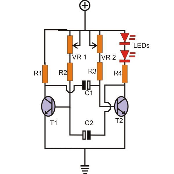
The circuit above makes up the base for the circuits below via appropriate modifications, optimizations, and additions.
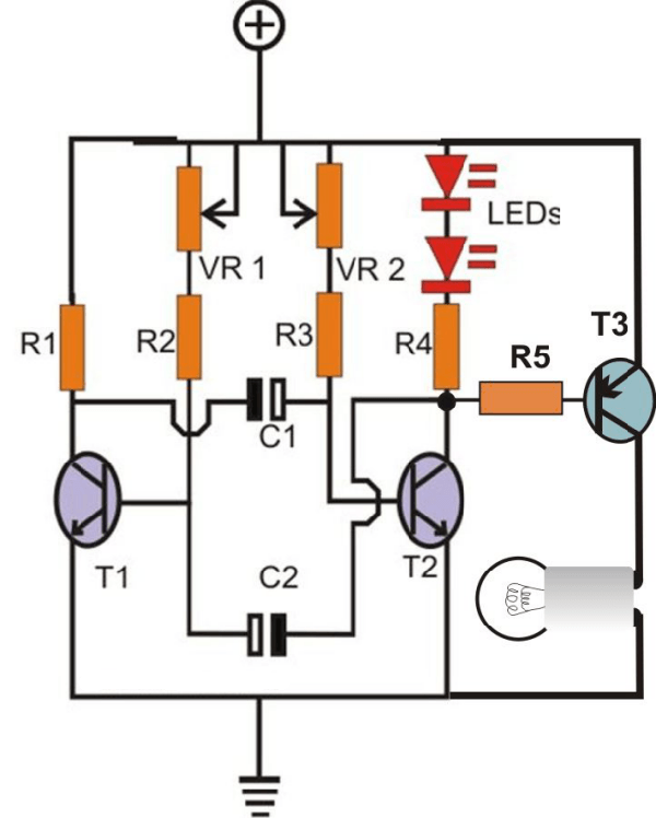
Provided that there, for instance, is a need to light and pulsate small torchlight, the simple modifying work illustrated in the below image is needed. By adjusting the circuit with a PNP power transistor and then activating it via Collector T2, the same torchlight will be turned into a flashing light simply. Certainly, the best effect requires an adjustment of the 2 Pots.
As discussed in the last part, lasers are welcomed recently by young people. Thus, this image 3 illustrates one of the simple methods to turn the circuit in the image above into flashing laser light. T3 and T4 construct a typical current-control configuration of the transistor, which is a must when the frail laser is involved. Section R6 will critically determine the threshold of current-limiting for safety during the operation of a laser. It is important because even a small wrong calculation may kill the expensive laser device in a second.
The formula below could be applied for R6 calculation:
U = 0.6/Ilaser,
In this formula, U refers to the operating voltage of the circuit and laser.
I refer to Maximum safe operating current for laser bulbs.
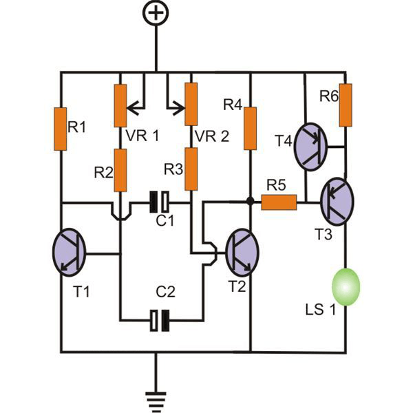
Image 4 illustrates the way to switch AC mains lamps to flashing lights with, the same, the above circuit. Now the triac constitutes the basic on and off element receiving the demanded gate pulses from the T2 collector.
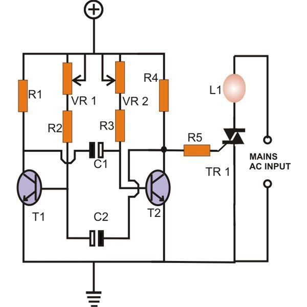
In general, via the circuit diagrams above, it is simple to modify the diversity of ordinary lights.
Parts List
R1, R4, R5 = 680 Ohms,
R2, R3 = 10K
VR1, VR2 = 100K pot
T1, T2 = BC547,
T3, T4 = BC557
C1, C2 = 10uF/25V
Triac = BT136
LEDs = as per choice